CAN transceiver is a bridge connecting CAN control system and CAN bus network. What parameters should be paid attention to when selecting CAN transceiver? This article will give you an in-depth understanding of each parameter of the transceiver and its significance in practical applications.
Input characteristics
For isolated CAN transceivers, the input primarily refers to the input characteristics of the side connected to the CAN controller, including the power input and signal input.
According to the CAN interface voltage of the controller, the CAN module with 3.3V or 5V power supply can be selected. The normal input range of the isolated CAN module is VCC±5%. The main consideration is that the CAN bus level can be kept within the typical value range, and also the secondary The CAN chip operates near the nominal supply voltage.
For a separate CAN transceiver chip, the VIO pin of the chip needs to be connected to the same reference voltage as the TXD signal level to match the signal level. If there is no VIO pin, the signal level should be kept consistent with VCC. When using the CTM series of isolated transceivers, the signal level of the matching TXD needs to match the supply voltage, ie 3.3V standard CAN controller interface or 5V standard CAN controller interface.
2. Transmission characteristics
The transmission characteristics of the CAN transceiver are mainly three parameters: transmission delay, reception delay, and cyclic delay.
When choosing a CAN transceiver, we think that the smaller the delay parameter, the better, but what are the benefits of small transmission delay? What factors limit the transmission delay of the CAN network?

Figure 1 CAN transceiver delay characteristics
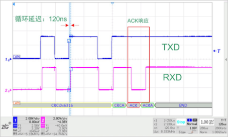
In the CAN protocol, the RXD is also monitoring the bus status while the transmitting node is transmitting data through the TXD. If the RXD monitor bit does not match the send bit, the node detects a bit error. If the monitoring in the arbitration field does not match the actual transmission, the node stops transmitting, that is, multiple nodes on the bus simultaneously transmit data, and the node does not obtain the data transmission priority. Also in the data checksum ACK response bit, RXD is required to acquire the data state of the bus in real time. For example, in normal network communication, the node is abnormal. In order to receive the ACK response reliably, it is necessary to ensure that the ACK bit is transmitted to the RXD register of the controller within a certain period of time. Otherwise, the sending node will detect a response error. The sampling position is set to 70% at 1 Mbps. Then, from the TXD transmission, when the RXD receives the ACK bit, the controller will sample at the 70% time point of the start of the ACK bit time, that is, the cyclic delay of the entire CAN network is less than 700 ns. In isolated CAN networks, this parameter is primarily determined by the isolator delay, CAN driver delay, and cable length. Therefore, a small delay time contributes to reliable sampling of the ACK bits, increasing the bus length. Figure 2 shows the ACK response for communication between two nodes using the CTM1051KAT transceiver. The typical delay time inherent in a transceiver is approximately 120 ns.

Figure 2 CAN network ACK response
3. Bus level
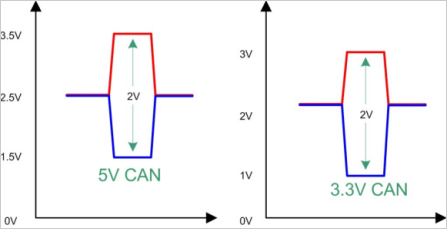
In the high-speed CAN network specified in ISO11898-2, we usually care about the amplitude of the differential signal, which is the key to bus data transmission. At present, there are a few CAN transceiver chips that support 3.3V power supply, which can be directly applied to the 3.3V control system. Due to the structural characteristics of the CAN transceiver, the CANH and CANL levels are related to the power supply. Although the differential values ​​of the CAN transceiver output of the 5V and 3.3V operating voltages are the same, the amplitude of the 3.3V transceiver CANH and CANL relative to the reference GND. The value is low, about 2V, such as TI's TCAN334. Using these two different transceiver networks, a single twisted pair or shielded twisted pair single point grounding is fully functional. If a double-shielded twisted pair cable is used, since CANH, CANL, and GND are all signal connections, communication errors may occur due to different bus voltages of the two transceivers. Therefore, the actual use should avoid direct connection of its GND.

Figure 3 transceiver bus level
4. Explicit timeout
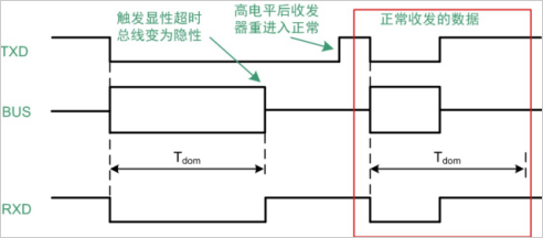
The increase in dominant timeout is mainly to prevent the TX bus network from being in the "0" state for a long time due to hardware or software failure. Keeping TXD at "0" means that the CAN network is dominant, and all nodes of the entire network cannot send and receive data, that is, the bus is in a 瘫痪 state. The dominant timeout can be avoided by the hardware timing of the transceiver. As shown in Figure 4, Tdom is the dominant timeout period. The transceiver starts timing every time TXD is "0". When the Tdom is exceeded, the transceiver releases the bus internally, and the bus state is at a recessive level. The dominant timeouts of different transceivers are different. The actual application needs to consider the influence of the explicit timeout on the minimum baud rate of the bus. The CAN protocol stipulates that the error frame can have up to 11 consecutive dominant bits. To avoid the dominant timeout, it can calculate the lowest baud rate actually used according to the minimum dominant timeout of the transceiver. BPSMin = 11/Tdom_min. If the dominant timeout of the CTM1051Q is 0.3ms, the minimum baud rate is calculated to be 11/0.3=36.67kbps.

Figure 4 explicit timeout timing
5. Sleep wake up
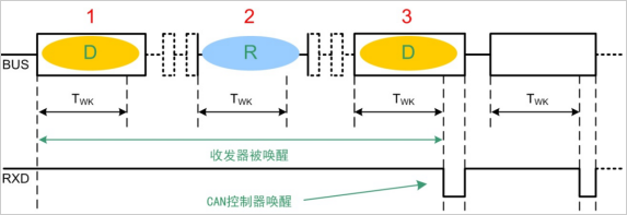
ISO11898-5 shows a high-speed CAN bus unit in low-power mode. The CAN transceiver can be in sleep mode to reduce power consumption and wake up the transceiver with a certain bus timing. Figure 5 shows the wake-up timing diagram of CTM1044KAT. In the sleep state, when the length of the bus is longer than the three dominant, recessive, and dominant levels of TWK, the transceiver in the sleep state is awakened, any encountered in the middle. Interference signal levels less than TWK will be filtered by hardware. TWK is defined to enable the transceiver to receive wake-up signals only safely and reliably, avoiding false triggers due to bus interference. After receiving the RXD signal, the CAN controller can trigger the wake-up controller through software setting to further set the module STB pin to enter the normal working mode. In this awake mode, when all nodes of the bus are in a sleep state, all nodes will be woken up as long as a node on the bus signals.

Figure 5 sleep wake-up sequence
6. Summary
The selection of CAN transceivers has a lot of knowledge, which is related to the stability and reliability of the overall CAN network. To ensure the stability and reliability of the networking network, you can choose the current mainstream fully isolated CAN transceiver module. Zhiyuan Electronics released the first isolated CAN/RS-485 transceiver in China in 2003, and has accumulated bus isolation technology for nearly 20 years. At present, CTM series isolated CAN transceivers cover all CAN-bus communication protocols such as CAN2.0A, CAN2.0B, fault-tolerant CAN and CAN FD, and the transmission rate supports up to 1Mbps. It is the leading brand of isolated CAN transceiver industry in China. Zhiyuan Electronic Isolation Transceiver has built-in complete isolated DC-DC circuit, signal isolation circuit, CAN bus transceiver circuit and bus protection circuit. It has higher integration and reliability and is suitable for occasions requiring high stability bus communication. Help users improve the level of bus communication protection.
Roll To Roll Fabric Printing Machine
Roll To Roll Fabric Printing Machine,Small Size Printing Equipment,Cloth Printing Machines,Direct Textile Printer
Shenzhen Textalk Graphic Technology Co.,Ltd , https://www.textalkdigital.com